
# Articles
# Get Started with C# HLF
The HLF library for C# offers many useful functions for creating structures in RFEM and RSTAB, some of which will be used in the following example.
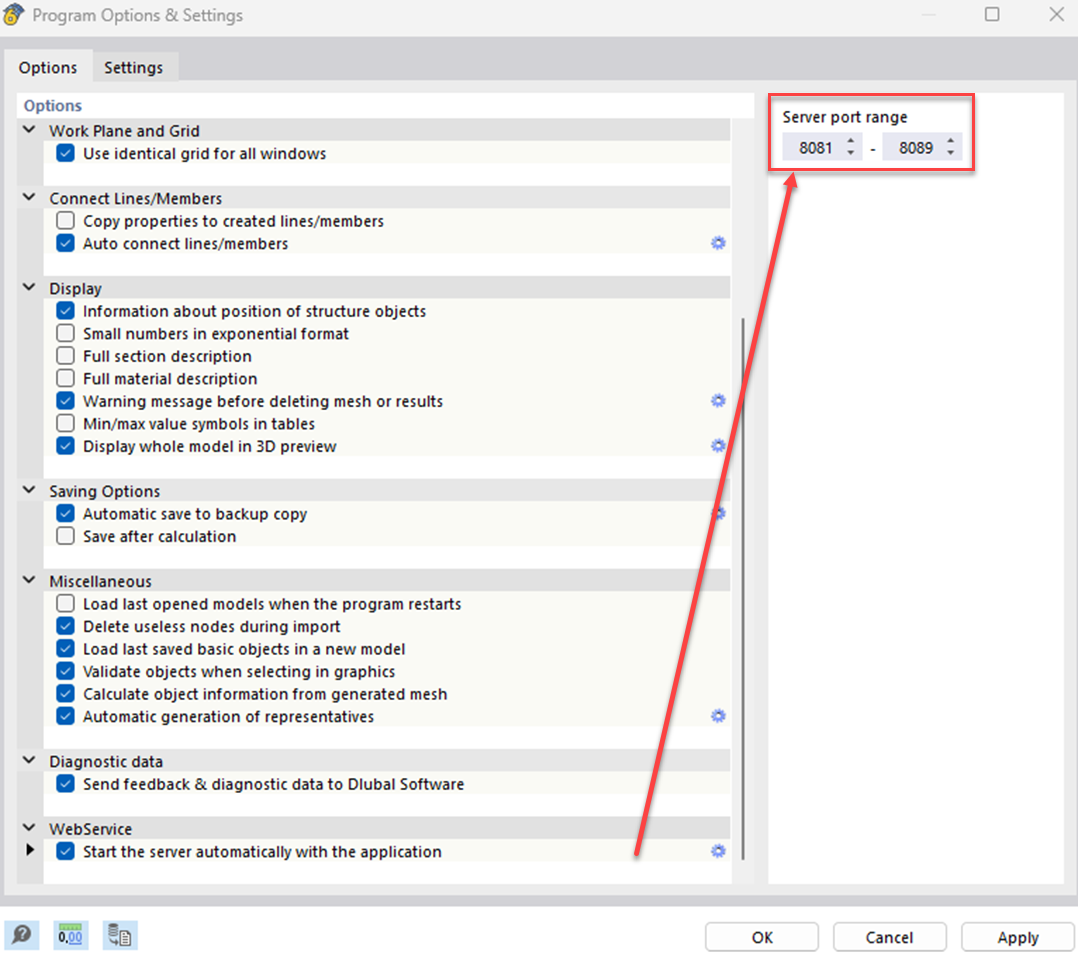
Before the programmed code can be used, a connection to the program is required. To do this, one of the available ports must be set as the address. The default address of RFEM/RSTAB is http://localhost:8081 (opens new window). This can be changed in the program options if necessary.
In the next step, various objects such as nodes, lines and members can be created with the help of the available functions in the C# library. The library includes classes for all available objects. With the help of parameters, the properties of the objects can be determined and specified. The number of parameters can vary depending on the application. The following example of a node shows how objects can be defined:
node newNode = new()
{
    no = nodeId,
    coordinates = new vector_3d() { x = xVector, y = 0.0, z = 0.0 },
    coordinate_system_type = node_coordinate_system_type.COORDINATE_SYSTEM_CARTESIAN,
    coordinate_system_typeSpecified = true,
    comment = "node for beam"
};
The definition of lines, areas and other objects is done analogously. It should be noted that for certain attributes an associated "Specified" attribute must also be defined and set to "true".
# Practice Example
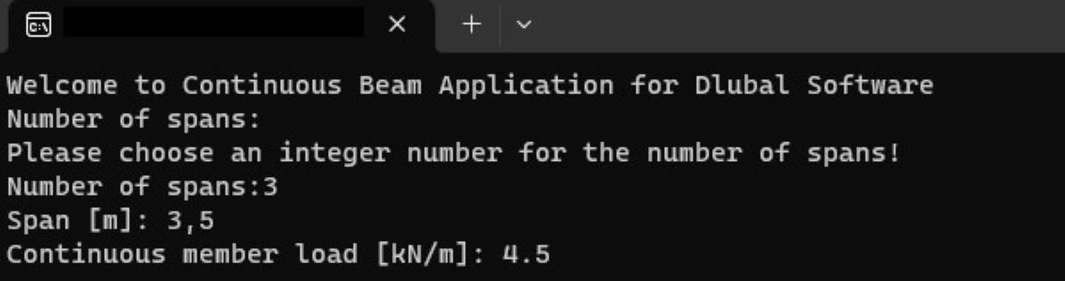
This example shows how to create a continuous beam with constant line load. The number of fields, span and size of the line load can be defined variably via the user input. First, the required variables are defined via the user input in the console. The system checks whether the user's input is compatible with the data type of the respective variable. If the input is incorrect or empty, an error message appears in the console. During programming, care must be taken to ensure that decimal numbers can be entered using both dot and comma notation in order to minimise the susceptibility to errors during input.
# Connection to RFEM/RSTAB
The following code attempts to establish a connection with RFEM/RSTAB within a Try-Catch-Block:
var logger = LogManager.GetCurrentClassLogger();
string CurrentDirectory = Directory.GetCurrentDirectory();
try
{
    application_information ApplicationInfo;

    try
    {
        // connect to RFEM6 or RSTAB9 application
        application = new ApplicationClient(Binding, Address);
    }
    catch (Exception exception)
    {
        if (application != null)
        {
            if (application.State != CommunicationState.Faulted)
            {
                application.Close();
                logger.Error(exception, "Something happened:" + exception.Message);
            }
            else
            {
                application.Abort();
                logger.Error(exception, "Communication with RFEM faulted:" + exception.Message);
            }
        }
        Console.WriteLine(exception.ToString());
    }
    finally
    {
        ApplicationInfo = application.get_information();
        logger.Info("Name: {0}, Version:{1}, Type: {2}, language: {3} ", ApplicationInfo.name, ApplicationInfo.version, ApplicationInfo.type, ApplicationInfo.language_name);
        Console.WriteLine("Name: {0}, Version:{1}, Type: {2}, language: {3} ", ApplicationInfo.name, ApplicationInfo.version, ApplicationInfo.type, ApplicationInfo.language_name);
    }
}

string modelName = "MyTestModel";
string modelUrl ="";
ModelClient model = new ModelClient(Binding, new EndpointAddress(modelUrl));
For establishing a connection, the program must be opened before executing the code. After a successful connection, the program information is displayed in the console and a new model with a user-defined name is created in RFEM/RSTAB.
# Definition of the Basic Objects
In the next step, the material and cross-section of the continuous beam can be defined. It is important that the names correspond to the names in the RFEM material or cross-section library.
material materialConcrete = new material
{
no = 1,
name = "C20/25 | EN 1992-1-1:2004/A1:2014"
};
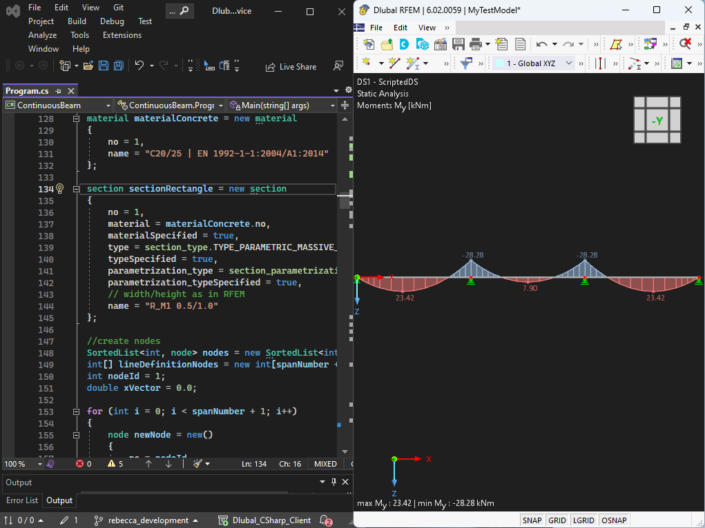
section sectionRectangle = new section
{
no = 1,
material = materialConcrete.no,
materialSpecified = true,
type = section_type.TYPE_PARAMETRIC_MASSIVE_I,
typeSpecified = true,
parametrization_type = section_parametrization_type.PARAMETRIC_MASSIVE_I__MASSIVE_RECTANGLE__R_M1,
parametrization_typeSpecified = true,
name = "R_M1 0.5/1.0"
};
Loops are used to create the various objects (nodes, lines, bars) and organise them in lists. The nodes are defined depending on the user-defined number of fields and transferred to the list "lineDefinitionNodes". This list is later used to create lines based on their definition nodes. If an RSTAB model is to be created, it is used to define the members by their definition nodes. When using RFEM, on the other hand, the members are defined by lines.
SortedList<int, node> nodes = new SortedList<int, node>();
int[] lineDefinitionNodes = new int[spanNumber + 1];
int nodeId = 1;
double xVector = 0.0;

for (int i = 0; i < spanNumber + 1; i++)
{
    node newNode = new()
    {
        no = nodeId,
        coordinates = new vector_3d() { x = xVector, y = 0.0, z = 0.0 },
        coordinate_system_type = node_coordinate_system_type.COORDINATE_SYSTEM_CARTESIAN,
        coordinate_system_typeSpecified = true,
        comment = "concrete part"
    };
    nodes.Add(nodeId, newNode);
    lineDefinitionNodes[i] = nodeId;
    xVector = xVector + span;
    nodeId++;
}

// create lines
int lineId = 1;
SortedList<int, line> lines = new SortedList<int, line>();

for (int i = 0; i < spanNumber; i++)
{
    line newLine = new()
    {
        no = lineId,
        definition_nodes = new int[] { lineDefinitionNodes[i], lineDefinitionNodes[i + 1] },
        comment = "lines for beams",
        type = line_type.TYPE_POLYLINE,
        typeSpecified = true,
    };
    lines.Add(lineId, newLine);
    lineId++;
}
After all basic objects have been created, two different nodal supports are defined. The nodal support at the first node is to be fixed, while the remaining support is to be movable in the X-direction. The definition nodes for the different support types are each placed in a separate list.
nodal_support support1 = new()
{
    no = 1,
    nodes = supportedNodes1.ToArray(),
    spring = new vector_3d() { x = double.PositiveInfinity, y = double.PositiveInfinity, z = double.PositiveInfinity },
    rotational_restraint = new vector_3d() { x = double.PositiveInfinity, y = 0.0, z = double.PositiveInfinity }
};

nodal_support support2 = new()
{
    no = 2,
    nodes = supportedNodes2.ToArray(),
    spring = new vector_3d() { x = 0.0, y = double.PositiveInfinity, z = double.PositiveInfinity },
    rotational_restraint = new vector_3d() { x = 0.0, y = 0.0, z = double.PositiveInfinity }
};

nodalSupports.Add(support1);
nodalSupports.Add(support2);
# Transmitting the Objects to RFEM
In order for the created objects to be available in RFEM/RSTAB, they must first be passed to the program. This is done between the two functions "model.begin_modification" and "model.end_modification" using object-specific functions of the HLF library. Using foreach loops, all objects of a type are passed to the program.
try
{
    model.begin_modification("Geometry");
    model.set_material(materialConcrete);
    model.set_section(sectionRectangle);

    foreach (KeyValuePair<int, node> nodeItem in nodes)
    {
        model.set_node(nodeItem.Value);
    }
    foreach (KeyValuePair<int, line> lineItem in lines)
    {
        model.set_line(lineItem.Value);
    }
    foreach (KeyValuePair<int, member> memberItem in members)
    {
       	model.set_member(memberItem.Value);
    }
    foreach (var nodalSupport in nodalSupports)
    {
        model.set_nodal_support(nodalSupport);
    }
}
catch (Exception exception)
{
    model.cancel_modification();
    logger.Error(exception, "Something happened while creation of geometry" + exception.Message);
    throw;
}
finally
{
    try
    {
       	model.finish_modification();
    }
    catch (Exception exception)
    {
        logger.Error(exception, "Something went wrong while finishing modification of geometry\n" + exception.Message + "\n");
         model.reset();
    }
}
# Definition of the Loads
The load cases, load combinations and design situations are created in a similar way to the basic objects and then transferred to the programme. Afterwards, the member load, which was previously specified by the user, can be created:
SortedList<int, member_load> member_loads = new SortedList<int, member_load>();
int member_load_id = 1;

for (int i = 0; i < spanNumber; i++)
{
    member_load newMemberLoad = new()
    {
        no = i + 1,
        members_string = (i + 1).ToString(),
        members = new int[] { i + 1 },
        load_distribution = member_load_load_distribution.LOAD_DISTRIBUTION_UNIFORM,
        load_distributionSpecified = true,
        magnitude = memberLoad * 1000,
        magnitudeSpecified = true,
        load_is_over_total_length = true,
        load_is_over_total_lengthSpecified = true,
    };
    member_loads.Add(i + 1, newMemberLoad);
    member_load_id++;
}
In addition to uniformly distributed loads, trapezoidal and parabolic loads, among others, are also possible.
# Calculation and Result Output
The function model.calculate(all) performs all calculations in RFEM. After successful calculation, the results are displayed in the console in this example. The HLF library for C# also allows results to be exported to XML or CSV files. Finally, the model.save() function can be used to save the model in the file path specified in brackets:
//save the model before closing
model.save(CurrentDirectory + @"\testmodels\");
application.close_model(0, true);
# Summary
In the shown example, the advantages and the ease of use of the C# library become clear. Through user-defined inputs, the structure can be quickly adjusted, which saves a lot of time when creating static systems in RFEM 6 and RSTAB 9. The HLF library of C# also offers many other functions that enable the creation of complex systems.